Water hammer due to valve closing is unfortunately a common risk as valve closing dramatically reduces flow – “blocking” the water path. In this short blog, we look at the problem and recommended solutions.
Problem:
Water hammer caused by valve slamming at closing.
Valve: IR-2″-100 series, commanded by external pressure (no specific application is detailed)
Working pressure: 50 meters / 73 psi
Command pressure: Not specified
Flow: 4 l/s (14.4 m3/h) / 63.4 gpm
Flow velocity: 2m/s / 6.5 f/s
Possible Cause:
Based on available information, slamming is assumed to be caused by one or both of the following reasons:
Command pressure is much higher than valve inlet pressure
Pneumatic command
Solution:
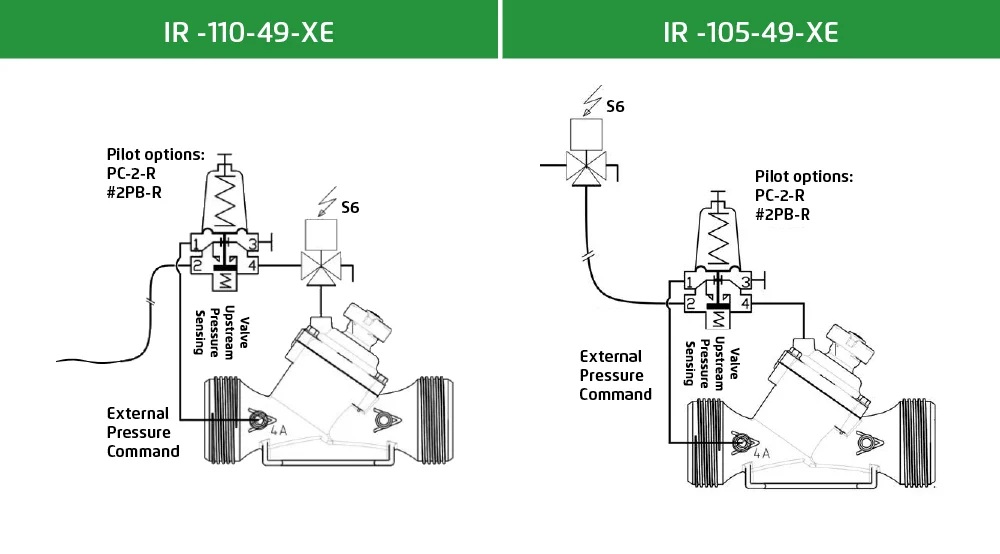
We propose adding feature #49 (upstream pressure rise prevention at closure) to existing control loop shown in the illustration below:
Pilot will restrict flow into control chamber as pressure upstream climbs towards set point (cutting it completely if it rises above set point).
Features & Benefits:
Dynamic closing speed in responds to pressure rise (higher upstream pressure = bigger flow restriction through the pilot and slower closing speed)
Closing maneuver freeze if upstream pressure rises above set point (pilot will momentarily cut command pressure flow until upstream pressure returns to permitted values)
Closing maneuver resumes once upstream pressure drops below set point.
Unrestrained closing speed during most of actuator’s stroke – minimum effect on total closing maneuver duration (as long as upstream pressure remains within normal parameters, closing speed is unrestricted, unlike a solution based on a needle valve which restrains flow regardless of pressure fluctuations)
Lower risk of loop clogging (for small control chamber displacement volume – a solution based on needle valve will offer very narrow flow through cross section that can clog by particles smaller than loop inlet filter. A pilot will only reduce passage upon pressure rise, opening the pass once pressure stabilizes, washing trapped particles out of the loop)
Setting Considerations:
In 3 way loop with remote control – Pilot setting should be higher than maximum static upstream pressure (to allow valve opening) – if not additional elements should be added to control loop
Pilot setting should be lower than nominal pressure of the installation (defined by the lowest pressure rating element installed upstream of the valve)
Control Loops:
This can be achieved using 3 different pilots – all equipped with remote sensing:
PC-2-R: 2 way pressure reducing with remote sensing
#2PB-R: 2 way pressure reducing pilot with remote sensing
PC-S-R: 2/3 way servo pilot with remote sensing
The loops below show the solution using PC-2-R or #2PB-R, with local or remote control (command pressure is external in both cases).
Interested in learning how flow control valves maintain a constant pre-set maximum flow regardless of fluctuating demand or varying system pressure? Read the blog to learn more about the valves and flow control applications in irrigation systems.