Hydraulic Flow Control
BERMAD Flow control & Pressure Reducing valve is an important…
Did You Update BERMAD Connect Already? Check It Out
Update BERMAD Connect Today! Check It Out


Flow control valves are designed to maintain a constant pre-set maximum flow regardless of fluctuating demand or varying system pressure. Flow limiting is required at the outlets from main systems to consumers like secondary systems (main line to hydrant line; hydrant line to distribution line), reservoirs, etc. in order to protect the supplying system from over consumption. Consumption is determined by user demand downstream from the flow control valve — according to the number of emitters in the field and their flow data, number of users irrigating at the same time, exterior components like reservoirs and backup systems.
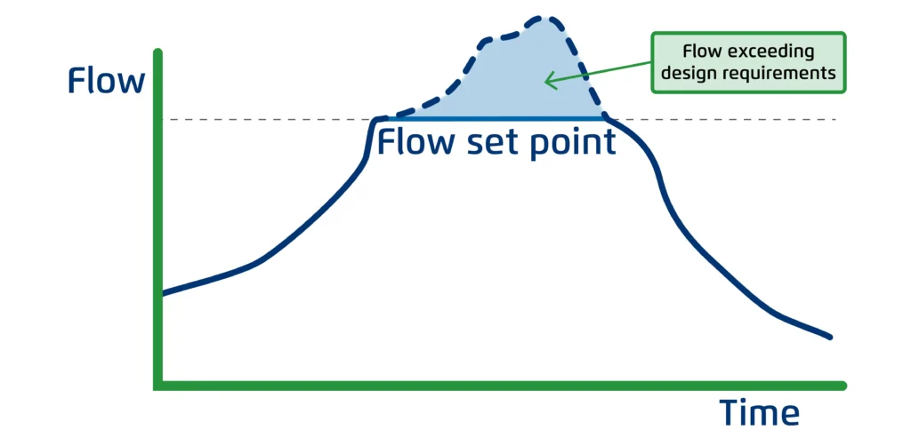
System flow versus time with flow limiting valve and without (dashed line)
Unable to control users, designers are using flow control valves to ensure that the flow won’t exceed significantly above design flow. By limiting the flow, we protect the supply system from excess demand, prioritizing it over users when they attempt to consume more than the system’s specifications.
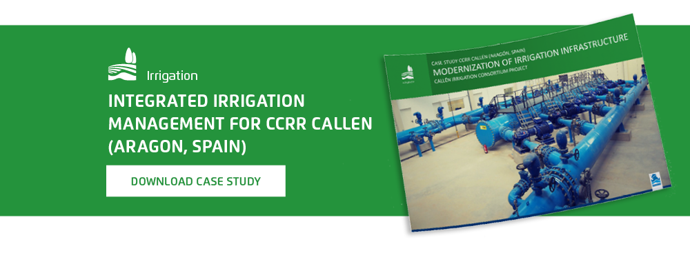
<< Download the free case study on Integrated Irrigation Management >>
Irrigation modernization is aimed at saving water and energy by improving irrigation infrastructure — upgrading from flood irrigation to pressurized systems and by doing so, increasing irrigation efficiency & optimizing the usage of existing water resources. Hydraulic design of pressurized irrigation systems is based on two main parameters: flow rate & pressure. Based on these parameters, the entire system design is established: pumps are selected, the type & size of the filtration system are determined, main & distribution lines materials & diameters are defined, in addition to the required number, dimensions & location of reservoirs.
Using smaller flow along longer time makes the “irrigation scheme of operation” (irrigation shifts) a main design tool to reduce the required energy and system pipes & components diameter. The irrigation is then divided to shifts that allow energy & initial expense saving. This detailed design is based on the fact that flow rate in the main line and required flow rate per each irrigation shift is known.
So, if we don’t limit the flow in systems with multiple users, the uncontrolled consumption will result with a significant pressure drop in the entire system. This can lead to pump and component cavitation, power consumption overload, air generation, dirt suction, etc. A significant deviation of more than 10-15% from the known design parameters of flow and pressure will result in an irrigation system that functions very poorly. This can be avoided by implementing flow limiting valves.
Higher field demand than the designed flow can take place due to:
a) Limiting the flow rate at the outlet to the plot in order to protect the pump from over capacity, overload & cavitation conditions and to maintain the design flow rate.
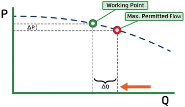
b) Limiting the flow on the main line in order to protect the pump & system from overload and cavitation to maintain a flat pump curve as shown in the graph below. When demand is significantly higher than design:
Flow control for systems that are emptied between irrigation shifts such as:
The following video demonstrates an irrigation machine (centre pivot) fill up process:
Flow control in order to prevent media “run-off” from the filter, screens and potential filter element collapse, in addition to saving water & energy.
The following video demonstrates different control valves required in a filtration system among them, flow control valves:
Level control valves regulate when the water level in the reservoir drops. When this happens at the same time that the system is operating/irrigating, it might cause a pressure drop for all other users. So, by limiting the filling flow of the reservoir, we protect the system from this kind of pressure drop. In addition, using a flow & level control valve can provide protection for both valve & reservoir from high filling flow & cavitation conditions.
Should the valve set flow be equal to the designed nominal flow; the valve will constantly be in throttling mode creating higher head-loss (lower downstream pressure at the field) and more demanding operating conditions, risking valve cavitation damage.
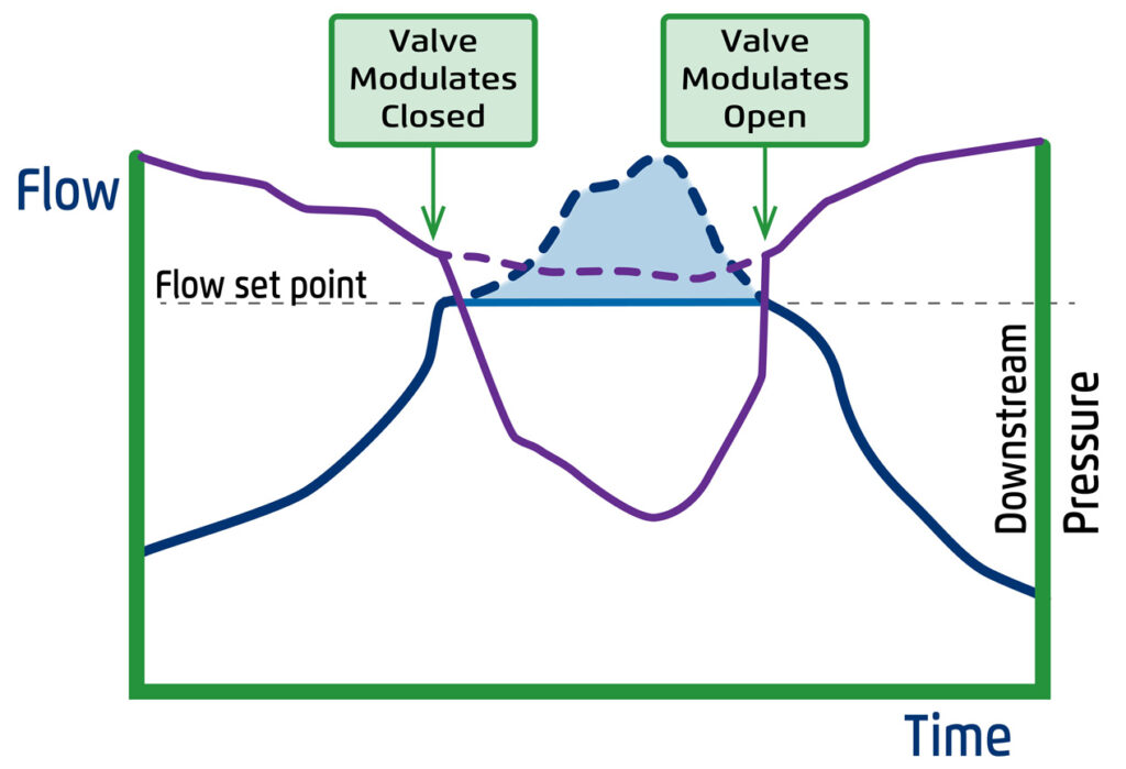
See the graph to the left demonstrating the effect of consumers over demand (light blue area) on valve downstream pressure (purple line) when valve throttles to maintain preset flow (blue line). Note: the dashed purple line demonstrates downstream pressure without flow control; the purple line represents pressure, the blue line represents flow.
Bermad strongly recommends calibrating the flow control valve to 10-15% above the plot nominal design flow for the following reasons:
Attached to the valve upstream, the machined orifice plate is sized to create known differential pressure for a given flow rate.
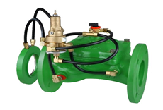
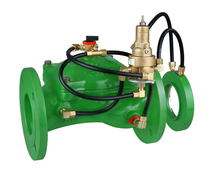
Bermad Model 470-U Flow Control Valve with ΔP Orifice Flow Sensor. Sensing this differential pressure, the pilot controls the main valve:
The internal differential pressure duct is actually an internal device, installed inside the valve, designed to sense a known differential pressure for a given flow rate. The TubeOrifice’s benefits over the standard orifice are:
Located at the valve downstream, orifice differential pressure can be determined by controlling orifice inlet pressure only, as orifice downstream pressure is constant = to reservoir water level. The valve limits the reservoir filling flow by simply reducing the pressure upstream from the orifice (between the orifice & the valve), thereby prioritizing consumers over reservoir filling, and providing level control and valve cavitation protection.
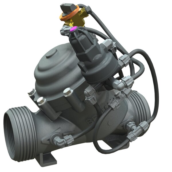
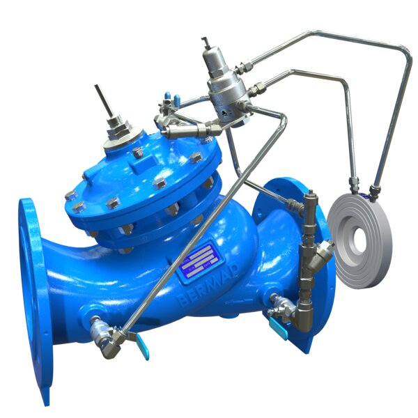
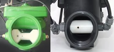
Threaded to a dedicated port on the valve body, the paddle type pilot provides 3-Way (or 2/3 Way) flow control capability. Located within the flow stream, the paddle of the pilot is designed to sense the force differential associated with flow velocity “hitting” a paddle. Paddle deviation from the “vertical position”, determines pilot control status to throttle close or to open the valve. The image shows a Bermad Flow Control Hydrometer Model 970-55 with Paddle-Type Pilot as flow sensor.
Note: For flow velocities below 1m/s, a 2/3-Way Servo Paddle-Type Pilot is recommended.
Outlet Management system Orissa, India
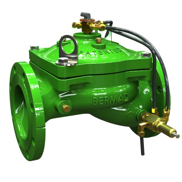
The photos below presents a typical outlet management system in India equipped with flow control & pressure reducing field valves (Bermad Model IR-2″L-172). Each valve controls irrigation of a plot belonging to a different farmer. The project includes 726 Outlet Management Systems (OMS), each including isolation valve, stone trap strainer, air valve, field control valve & automation.
The flow is controlled by 3-Way Paddle-Type Pilots.
Bermad is the chief supplier for this ongoing project with about 3,500 polymeric valves; each was tested & calibrated according to the design requirements at Bermad factory.
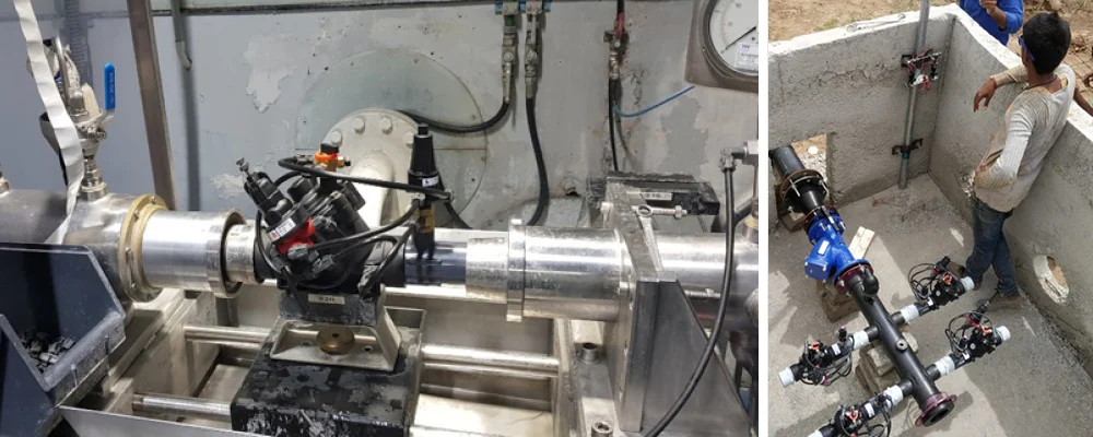
Image on the left shows Bermad Model IR-172 Flow Control & Pressure Reducing Valve on test bench for testing & calibration; the right image shows the OMS installation at the site, Orissa India.
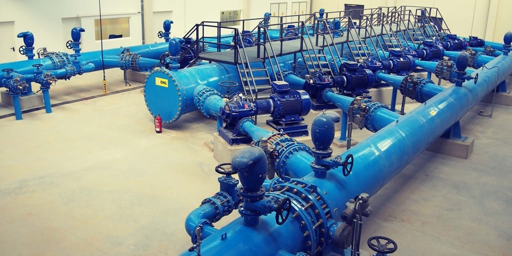
CCRR Callen in Spain is a 1,872 Ha irrigation consortium with 70 users who grow corn, barley, wheat and alfalfa. The consortium wanted to modernize its irrigation infrastructure because it was outdated, inefficient and required intensive manual operation.
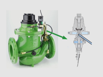
Bermad’s integrated irrigation solution for Callen included a main line & surge solutions as well as remote-controlled pressure reducing and flow-control hydrometers IR-972 to each plot.
The consortium remotely controls each hydrometer according to the designed irrigation shifts.
The flow control hydrometers IR-972 with paddle-type pilot are installed at the irrigation head in order to control:

We got your email. Now, let’s make it personal...