
Water Hammer Solution in Multistorey Building Applications
How to handle water hammer – pressure surges in high-rise…
Did You Update BERMAD Connect Already? Check It Out
Update BERMAD Connect Today! Check It Out


Whenever you are designing a pressure reduction station, it’s important to consider the extreme flows and pressures the valve may need to operate under. This defines the setup of your pipeline, and determines how you position your pressure reducing valves.
These considerations include the known conditions at the time of the installation – as well as the potential for change in operating conditions during the pipeline’s lifetime.
Some of the data you might need to determine if you require parallel valves include:
Once this data has been measured, it may produce an extremely wide range of flow data and pressures that a single valve may not be able to maintain.
Additionally, if the valve is positioned on a single feed line to the pressure zone – there is no simple way to isolate the valve for maintenance without turning off the flow of water.
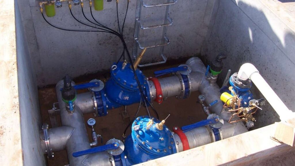
Under these circumstances, we recommend considering the valuable option of designing a station that caters for parallel pressure reducing valves.
The 720 series valves allows for operation at a range of pressures between zero and maximum flow.
This unique feature is engineered to ensure a high level of operation using a single valve, and has been a proven design over many years with great success. In most circumstances, a single 720 series valve has the capability to cater for a range of flow rates.
In 99% of circumstances, the designed flows operate between 0.1 to 6 l/s – conditions where a DN50 valve can operate perfectly.
However, in the rare event of a fire within the network, the flows will increase to 25 -30 l/s. In this instance, a parallel 100mm valve can take over when the low flow valve cannot cope with the increased flow rate.
When a valve sits idle with zero flow for extended periods of time, the large valve can collect idle water – which is not desirable from a water quality perspective.
From an operational point of view if there is accumulated debris in the inlet of the valve, it can make the valve questionable in its reliability and performance.
To ensure the valves are reliable for the long haul, it’s important that the valves operate regularly.
To support this, try fitting a flow stem to ensure that under peak daily flow the larger valve opens daily.
When this is set up, the valve operates regularly and reduces the potential for ‘dead water’ behind the larger valve.

As a rule, it’s important that the smaller of the valves are set approximately 10-20Kpa above the set point of the parallel larger valve, and fit V port plugs in the valve actuators for smooth transition flows without surging.
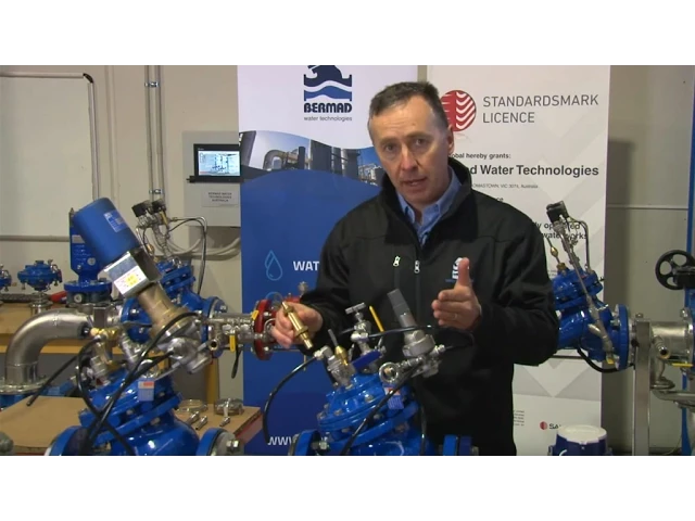
For more information on setting parallel valves, watch the following video discussing the operation of the parallel valve design.

Should you require design assistance on any pressure reducing station, please do not hesitate to contact your nearest Bermad office for assistance.

We got your email. Now, let’s make it personal...