The first and most dangerous is water hammer, which among other things, may be caused by the overly quick closing of a valve downstream (a typical occurrence with fire hose nozzle and hydrant valves). As this pressure surge occurs downstream of the pressure reducing valve, the valve will not be able to compensate and as a result, there will be overpressure which is sometimes quite extreme.
A sudden increase or spike in pressure experienced at pump start-up, or as a result of quick operating valves. With such fast changes in pressure, the pressure reducing valve (especially if it has a larger diameter) cannot react quickly enough to prevent a sudden pressure wave momentarily travelling downstream.
A pressure reducing valve failing to seal. This can be caused by firewater debris getting trapped on the valve’s sealing surface or even just wear-and-tear that prevents a watertight seal required in static no flow conditions. This allows for a gradual leak and build-up of high pressure downstream.
In certain cases during static no flow conditions, the pressure downstream of a pressure reducing valve can increase as a result of a rise in temperature. This is because the “Thermal Expansion” of the water and air within the piping is greater than the thermal expansion of the pipe itself, and thus causing a rise in pressure in the piping.
Sizing. While the NFPA and UL and FM standards stipulate the use of a minimum size pressure relief valve downstream, this is a minimum requirement and knowledgeable designers and manufacturers often recommend a larger size valve. The size should depend on the line size and working conditions. In the case of slow leaks, a smaller relief valve is sufficient. However, in the case of sudden pressure buildups or surges, a bigger relief valve is often required to release larger amounts of water quickly. For these reasons, it’s important to perform an analysis of system requirements and potential capacity of overpressure events when selecting the size of the pressure relief valves. The following is the BERMAD sizing table, which is applicable for normal or typical conditions:
As pressure relief valves are a safety requirement, it’s important to choose a pressure relief valve that is developed and manufactured by a well-known and reliable company. In addition, system developers should check that the pressure relief valve complies and is certified with all of the compulsory standards and is approved and listed by the accepted industry institutions.
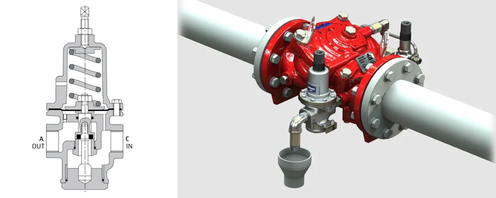
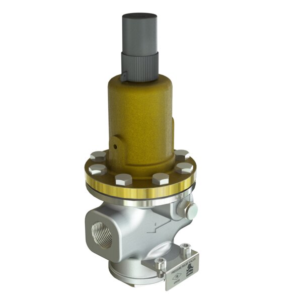
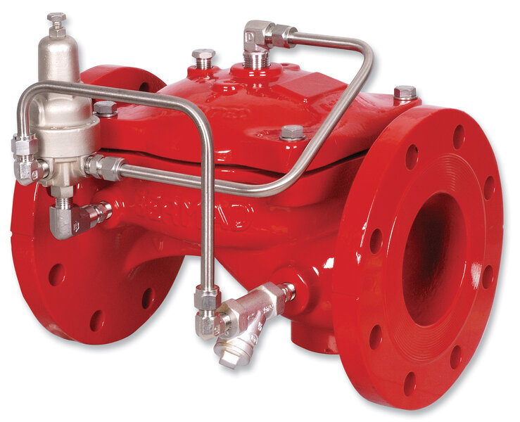
Opening characteristics. Relief valves can be divided into two main types, direct-acting and pilot-operated. Direct acting valves use a spring above the pressure sensing area. When the pressure force is higher than that of the spring, the valve will open. Pilot operated relief valves use a large main valve that will open when the auxiliary pilot senses a pressure higher than the set point.
The opening degree of direct-acting relief valves is somewhat limited by being directly related to the line pressure and the pressure range. These valves are quick opening, economical and simple in construction. As such, they are considered the valve of choice for lower relief flow requirements.
Also bear in mind that because direct-acting relief valves open directly against the main spring, their size and pressure range is limited. The reason for this is that with larger diameters and higher pressures, the spring becomes too big, cumbersome, and uneconomical.
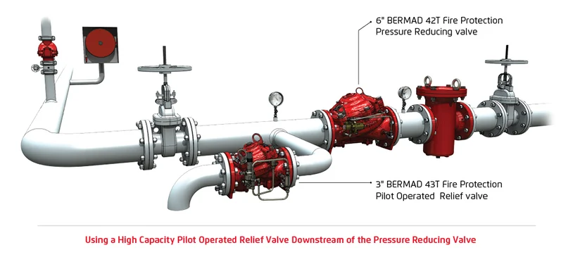
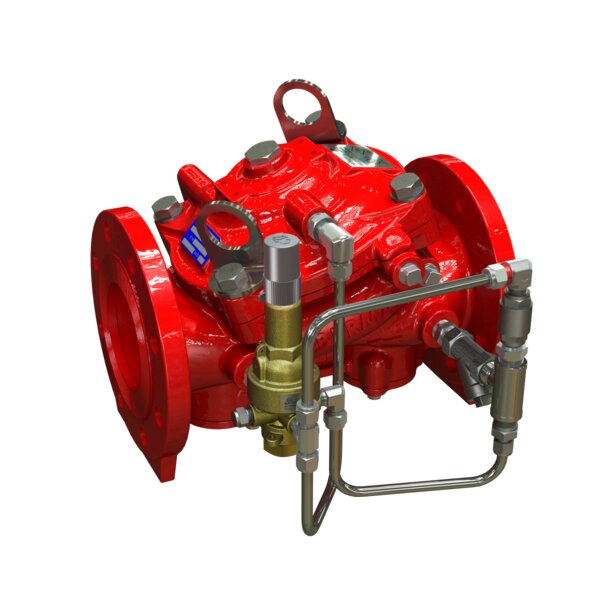
Pilot-operated relief valves are faster to reach full opening and have a steeper opening curve, which is more suitable for larger piping that may need fast high-capacity relief and where the valve needs to fully open quickly, as may be the case where there is a threat of surge conditions.
Accuracy. Both types of relief valves, if carrying the aforementioned certification, will have an accuracy that meets the necessary tolerance for pressure reducing relief:
Direct-acting relief valves – for use where a small flow capacity is required. These valves have a fast and accurate cracking point, but a limited opening characteristic. They are usually smaller and suited to low capacity relief duty.
Pilot-operated relief valves – for use in higher capacity and pressure applications, are considered more accurate across varied pressures and flows as the pilot’s sensing point is less exposed to the high flows during relief duty. Once the set pressure has been exceeded then these valves will continue to open fully until pressure returns to below the set pressure.