




BERMAD’s Advanced Solutions for Irrigation Districts Webinar
Watch the webinar recording and discover how irrigation districts can…
Did You Update BERMAD Connect Already? Check It Out
Update BERMAD Connect Today! Check It Out



In a recent BERMAD webinar, “The Optimal Approach to Irrigation Design,” our Global Irrigation Unit Manager, Yiftah Enav, presented BERMAD’s design approach when addressing the various considerations in project design.
Yiftah chose to start our Webinar Series by presenting basic terminology combined with theoretical rules-of-thumb referring to achieving optimal irrigation uniformity.
He then pointed out the gap between theory and practice regarding irrigation uniformity, reviewed some of the in-field conditions that affect or impair irrigation uniformity, and suggested practical solutions using control valves and components for long-term cost savings.
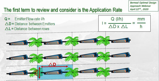
Q: How do you take into account that the application rate covers the emitter area when using drip or micros?
A: The application rate is always the flow per unit area of soil per unit of time. Some emitters cover the area above ground, while dripper wetting bulbs overlap underground, next to the roots.
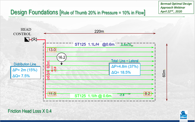
Q: If you use a non-compensating emitter, what’s the acceptable pressure & flow window difference to reach high uniformity (over 90%)?
A: The goal is to design for a maximum deviation of 10% between the emitter with the highest flow and the one with the lowest flow in the field. On the design map, it is more practical to calculate friction pressure losses, elevations, etc., based on emitter flow changes per location. This is why we follow the rule of thumb that a 20% change in pressure represents approximately a 10% change in emitter flow (or any orifice/hole).
BERMAD does not design irrigation projects. Our “design office” consists of the Application Engineering departments and our Sales Engineers team.
We encourage our colleagues and customers to contact us as early as possible in the design stage so we can combine our knowledge and experience to enhance the design’s uniformity, reliability, and efficiency.
Some questions referred to the Flush ‘n-Stop, Double Chamber valve performance, installation, and how it contributes to uniformity in different conditions.
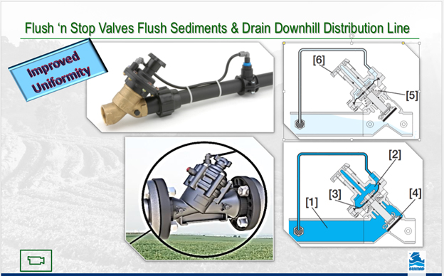
Q: At what pressure do the flushing valves open?
A: It is Normally Open and will close as the pressure rises to around 12m. It will reopen when pressure drops back to about 7m. A Flow Stem “M” is a standard feature to allow for pressure “build-up” by manually adjusting (once in a while) the flush flow rate.
Q: What is the recommended distance between the valve and the tubing pressure inlet?
A: Just a few meters are needed to prevent the high flow velocity near the valve from causing the dynamic pressure to drop too low, which would stop the valve from closing.
Q: Are Air Valves necessary to ensure the Flush ‘n Stop valve contributes to irrigation uniformity?
A: Kinetic air valve installed at the top of the distribution line will prevent vacuum & suction while shortening line drain time.
See videos of:
Flush ‘n Stop valve operating in the field
Combination Air Valve animation
Kinetic Air Valve animation
Q: When using CNL (anti-drain) emitters on a 30-50 meter downhill slope: in addition to installing a PRV at the beginning of each lateral, is it better to have pressure reducing valves along the subline (somewhere in the middle), or to continue using 2″ PRVs along the line every 10 meters?
A: Since all CNL emitters are Pressure Compensating, the designer benefits from a wider ΔP “corridor.” Therefore, depending on the lateral pressure rating, a 30m slope should not require additional pressure reduction along the line or at the start of each lateral. If the slope continues further downward, it is better to include a Pressure Reducing valve in the middle of the submain.
Double Chamber valves attracted lots of interest and many questions relating to the reaction time of valves to close and/or to regulate; size range, pressure rating and operating requirements; and how much more all these benefits cost.
Q: For the closing time, we have a problem with a big valve. Do we need to/can we change the diameter of the Pilots, Solenoid, and Accessories?
A: Usually, control accessories can be changed within a certain range, but this increases costs, makes installation more cumbersome, and leads to non-standardization. However, you can keep your standard accessories and use them on a Double Chamber valve that closes much faster, providing soft
closure (see table)
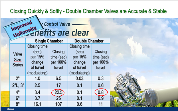
Q: I have a Single Chamber valve that takes a while to stabilize at set pressure. Until it stabilizes, it sends the PLC to error on high pressure.
A: Double Chamber valve that closes much faster providing soft closure (see table)
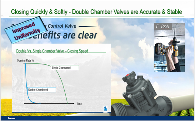
Q: Sometimes in pressure sustaining valves after filtration, we add a Galit relay, but it still takes more than 1 minute for DN>=150 to regulate.
A: Double Chamber valve that closes much faster from fully open to regulate mode (see table)
Q: Is there a PN16 Double Chamber 100 Series?
A: At this stage, only PN10. For PN16 & PN25, we have the Double Chamber 700 Series. For PN40, the Double Chamber 800 Series.
Q: Are there small diameter Double Chamber valves for small plots and pulse irrigation in greenhouses and so on?
A: Double Chamber 100 Series are available in sizes 1½”, 2″, 2″L, 2½”,
and 3″. The 4″ Double Chamber 100 Series is coming soon. For larger diameters up to 24″, 700 Series are available.
Q: What is the minimum pressure required for the diaphragm to respond in Single Chamber and Double Chamber Valves?
A: BERMAD Single Chamber valves need 3-5 meters to open and operate. Double Chamber valves, which do not require spring force to close, can open and function even at 1-2 meters.
Q: What is the cost difference between a single chamber and double chamber valve?
A: At this stage, for Double Chamber 100 Series around 30%
Q: When the flow rate drops to zero in a PRV, how is it ensured that the downstream set pressure is maintained? What operating conditions must be met to ensure that upstream pressure does not gradually “infiltrate” into the downstream side?
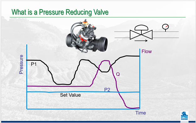
A: When the flow rate drops to zero, the amount of flow entering the line through the PRV is briefly greater than the flow leaving the line (which is zero). As a result, pressure builds up and increases in the line downstream of the PRV. The PRV pilot detects pressure above the set point and closes the PRV, attempting to bring the pressure back down to the set point. Since the flow is zero (Dead End), even when the valve is completely shut and drip-tight, the pressure will not decrease (assuming there are no leaks). The very definition of the PRV ensures that upstream pressure will not gradually “infiltrate” to the downstream side.

hbspt.cta._relativeUrls=true;hbspt.cta.load(2377786, ‘9eba2a87-544a-49aa-8c35-308a9637ce50’, {“useNewLoader”:”true”,”region”:”na1″});




We got your email. Now, let’s make it personal...