




BERMAD’s Advanced Solutions for Irrigation Districts Webinar
Watch the webinar recording and discover how irrigation districts can…
Did You Update BERMAD Connect Already? Check It Out
Update BERMAD Connect Today! Check It Out




Pressure and flow value optimization are an integral part of irrigation system design. With constant and often dramatic fluctuations in demand flow and supply pressure, valves and other components need to ensure dynamic pressure and flow control across the entire system.
In BERMAD’s webinar, “Pressure Reduction and Cavitation Prevention in Irrigation Systems,” our Global Irrigation Unit Manager, Yiftah Enav, presented BERMAD’s pressure reduction and cavitation prevention principles, methods, systems, and solutions. Yiftah shared useful insights about selecting the most effective pressure reducing control valves (PRVs) for long-term performance and cost savings.
Q: What is the difference between pressure reducing valves and proportional pressure reducing valves?
A: Pressure Reducing Valves (PRVs) are adjustable devices designed to consistently lower higher upstream pressure to a steady, lower downstream pressure, regardless of fluctuations in upstream pressure or demand flow.
Proportional Pressure Reducing Valves (PPRVs) do not include a pilot and are therefore not adjustable. Based on the ratio between the effective areas of their diaphragm and closure, PPRVs continuously reduce higher upstream pressure to lower downstream pressure in a constant ratio.
Only double chamber valves can serve as PPRVs.
Q: Is the PD reduction factor 2.5 for all sizes?
A: The PD reduction factor is 2.5 in most of the series and sizes; however, the reduction factor can vary and can be found on our website, price lists and relevant product pages. Refer to the relevant reduction ratio table for each valve size and each valve series (100, 700).
Q: Can we use pressure reducing valves to lower static pressure? Can a PRV function when there is no flow?
A: Yes. When demand flow drops to zero, the flow entering the line through the PRV is briefly greater than the flow leaving the line (which is zero). As a result, pressure builds up and slightly increases in the line downstream from the PRV. The PRV pilot detects pressure above the set point and closes the PRV, attempting to bring the pressure back to the set point. Since the flow is zero (dead end), even when the valve is completely closed, the pressure will stay slightly above the set point (assuming there are no leaks), ensuring the PRV remains closed.
Q: It has been claimed that it’s not always possible for the PRV to maintain P2 pressure when flow stops suddenly compared to a direct acting PRV. For this purpose, a pressure relief valve is required downstream of the PRV. What is your response to this claim?
A: Direct acting PRVs may be quicker than hydraulic PRVs, but are clearly inferior in terms of head loss, added features (even close/open), sensitivity, accuracy, maintenance and still require a pressure relief valve to protect the system should the DPRVs jam or fail to seal.
To speed up response time, a downstream pressure gauge pilot can be added or, preferably, use a double chamber PRV.
Q: We set the PRV at P1 to maintain the required P2. In this situation, P1 is as per design (theoretically), but in reality, P1 changes due to partial operation of the area, variation in demand, pump operation, or leakage. What is the P2 pressure during this condition? Does it change (increase)? Do we need to go to the site again to set the pressure, or does it automatically maintain the P2 pressure? Also, what will happen to the flow during variation as P1 changes?
A: Pressure reducing valves are continuously controlled by a pressure reducing pilot that senses only P2. Any changes in demand and/or P1 that affect P2 are immediately detected by the pilot, causing its internal mechanisms to adjust and instantly throttle the valve closed (when P2 rises) or open (when P2 drops) to maintain the pilot setting.
The flow is determined by the system emitters and outlets, not by the PRV. In fact, the PRV automatically adjusts its opening rate to the actual demand (& P1), ensuring it is neither “too open” nor “too closed” so that the set P2 is always maintained.
Q: What are the practical differences between PRVs with two-way and three-way controls?Since a three-way loop is vented to atmosphere, will it affect the regulation stability of a diaphragm-actuated valve?
A: A three-way circuit is characterized by the pilot “selecting” the water route: P1 to control (closing) or control to vent (opening). This leads to using a very small volume of control water and results in two different behaviors:
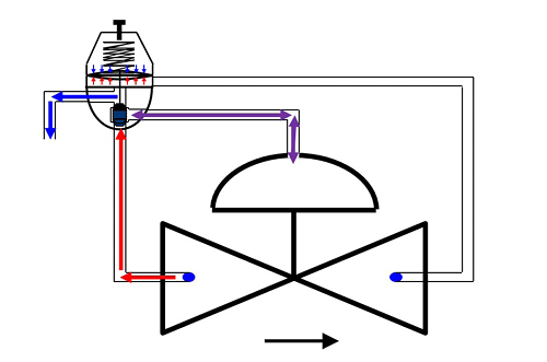
Q: What is the +/- pressure loss through a two-way control loop?
A: A two-way circuit is characterized by continuous flow from P1 through a restriction into the control chamber while the pilot “connects” the control chamber to the valve downstream, releasing chamber pressure as long as the valve is open. This leads to a relatively high volume of control water (0.2-0.5m³/h; 0.9-2.2gpm) and results in sensitivity to dirty water with the following hydraulic behaviors:
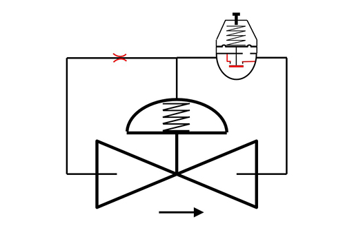
Q: What are the sizing criteria for circuit inlet restriction in two-way control?
A: The two-way control restriction should be smaller than the pilot water path to ensure stable and accurate regulation, with minimal added head loss and adequate reaction time. Essentially, the criterion is the size of the water path in the pilot, which is related to the valve size.
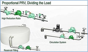
Q: What kind of applications can proportional pressure reducing valves be used for?
A: Gravitation downhill lines and/or when a high ΔP is required, necessitating two-stage pressure reduction to protect valves from erosion and cavitation and to provide backup protection for the system.
Q: While supplying water downhill from a balancing reservoir to multiple minor irrigation tanks (i.e. direct discharge to the atmosphere as explained in the case of pressure breaking tanks), which types of PRVs can be used? Can you please shed some light on this?
A: The recommended solution to replace pressure breaking tanks (PBTs) is to use PPRVs, which offer the following benefits:
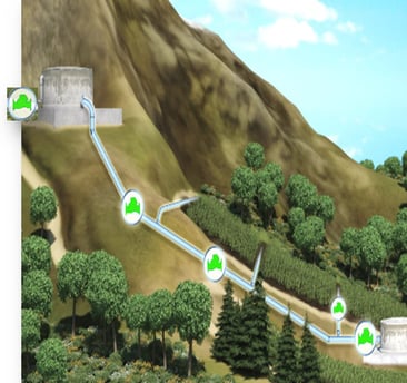
However, since the PPRV reduction ratio is constant, when the upstream pressure decreases due to friction head loss in the line, the downstream pressure also decreases. As irrigation demand flow changes, we need to position the PPRVs based on elevation differences (maximum upstream pressure) and the actual head at maximum flow/friction loss (minimum upstream pressure). Because each PPRV sets the pressure for the next PPRV, the design calculation can be somewhat complex. BERMAD has developed an Excel file that takes all parameters into account as a design support tool.
Q: What restrictions should be used for PPRVs?
A: PPRVs do not require any restrictions.
Q: Can a pressure reducing valve be designed to use flow as the variable instead of outlet pressure? In some cases, such as a gravity line, can a flow limiting or control valve be used as an alternative to a pressure reducing valve?
A: Several factors must be taken into account regarding pressure and flow in pressure reducing valves:
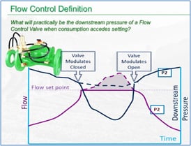
Should demand rise and P2 drop, the flow pilot will take control to limit the flow back to setting. Should demand drop, the flow pilot allows the valve to open. Should P2 rise, due to P1 increase or demand drop, the reducing pilot will take control and throttle the valve close.
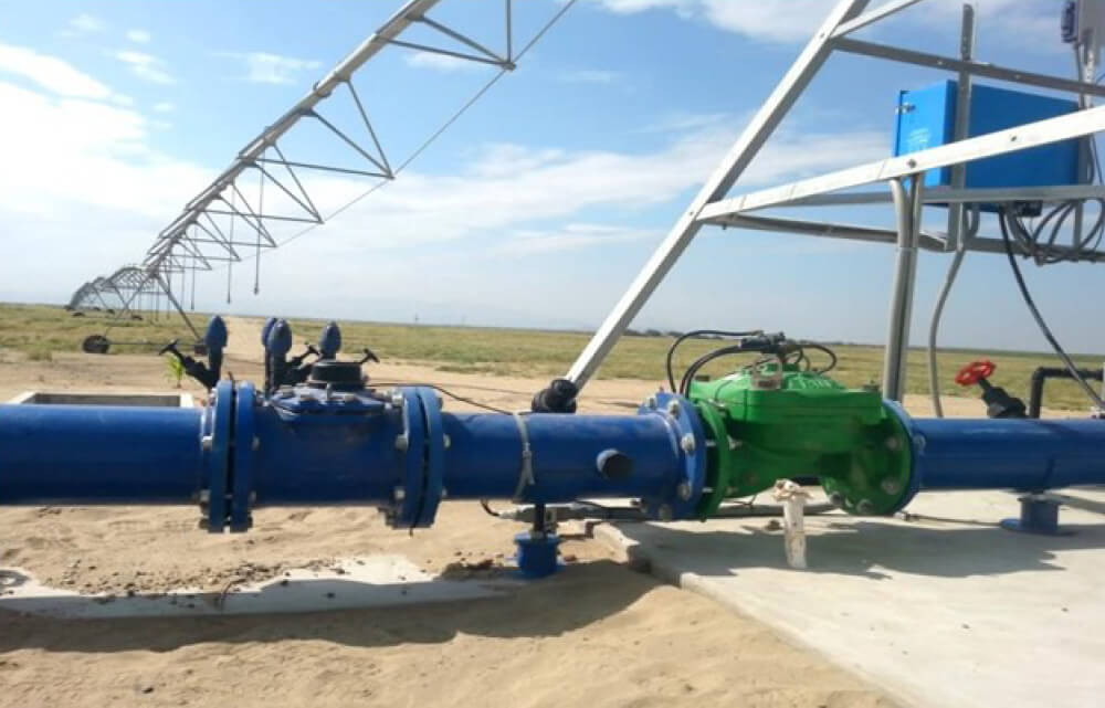
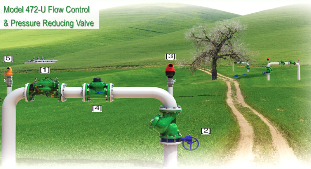
 When the flow pilot is in control, the valve closes, causing P2 to sometimes drop below the setting of the reducing pilot, which is not controlling the valve and cannot increase P2 as long as the demand is above the flow pilot setting. Therefore, it is recommended to set the flow pilot 15-20% above the nominal flow of the line.
Q: We installed four valves at the chak (main block) inlet where the inlet pressure (P1) is 60m, and the four sub-chak (plot) valves have different pressure (P2) requirements (meaning P2 for Valve 1 = 35m, Valve 2 = 25m, Valve 3 = 45m, Valve 4 = 50m). The sub-chak’s distribution pipe length, diameter, and elevation vary, but the same flow at the end of each sub-chak outlet is required. So, can we maintain the same flow at the end of the sub-chak outlet when P1 is constant but P2 varies?
A: The answer depends on whether the irrigation is pressurized and performed using drip, sprinklers, or jets (any emitter with a known flow), or if it is flood irrigation where the end of the distribution pipe is open to the atmosphere.
Q: Can we remotely change the PRV setting for pressure and flow?
A: Pressure reducing valves (and all hydraulic control valves) can accept two pilots set to different pressures. Installing a solenoid to “select” between the pilots will allow remote switching between pressure regimes.
Other options require adding devices to the pilot to enable dynamic remote setting. This will also require special controllers to enable analog control.
Q: What is the optimum range for valve travel in hydraulic pressure reducing valves?
A: Somewhere between 15%-30% depending on valve type, pressure & flow conditions, annual operating time and other factors. Applying a V-port plug forces the PRV to open more to better handle low flows. This allows the PRV to be ~15% open even when flow velocity drops to ~0.5m/s.
Q: In a direct pumping distribution network, how will the PRV respond when a power failure occurs and upstream pressure rises suddenly? Will it be able to maintain P2 downstream?
A: This is complex, as power failures involve multiple scenarios. If the question refers to a PRV on one of the outlets from a main line connecting a pump to a reservoir, we can expect the PRV to open when pressure drops due to a negative wave. In this case, it likely will not close quickly enough to maintain P2 if a positive wave occurs.
Q: Can the 400 series (single chamber, globe pattern) valve be used for pressure reducing applications? If yes, will it be more prone to cavitation compared to Y pattern valves (100 and 700 series)?
A: The 400 series can be used for pressure reducing applications. In fact, most of the metal PRV applications in irrigation are carried out by IR-400 Series or other single chamber valves. The IR-400 Series does not include a raised seat which makes them less resistant to cavitation damage than the IR-100 Series, due to it being made from composite material and the IR-700 Series which incorporates a raised stainless-steel seat. The Y Pattern also contributes to better cavitation resistance and ~25% better flow performance compared to standard globes.

hbspt.cta._relativeUrls=true;hbspt.cta.load(2377786, ’15c4f5d2-dd4d-497d-a39e-2137ccffbc5b’, {“useNewLoader”:”true”,”region”:”na1″});




We got your email. Now, let’s make it personal...